Testing Protocols by Greg Viggiano

Ultimate Analogue Test LP

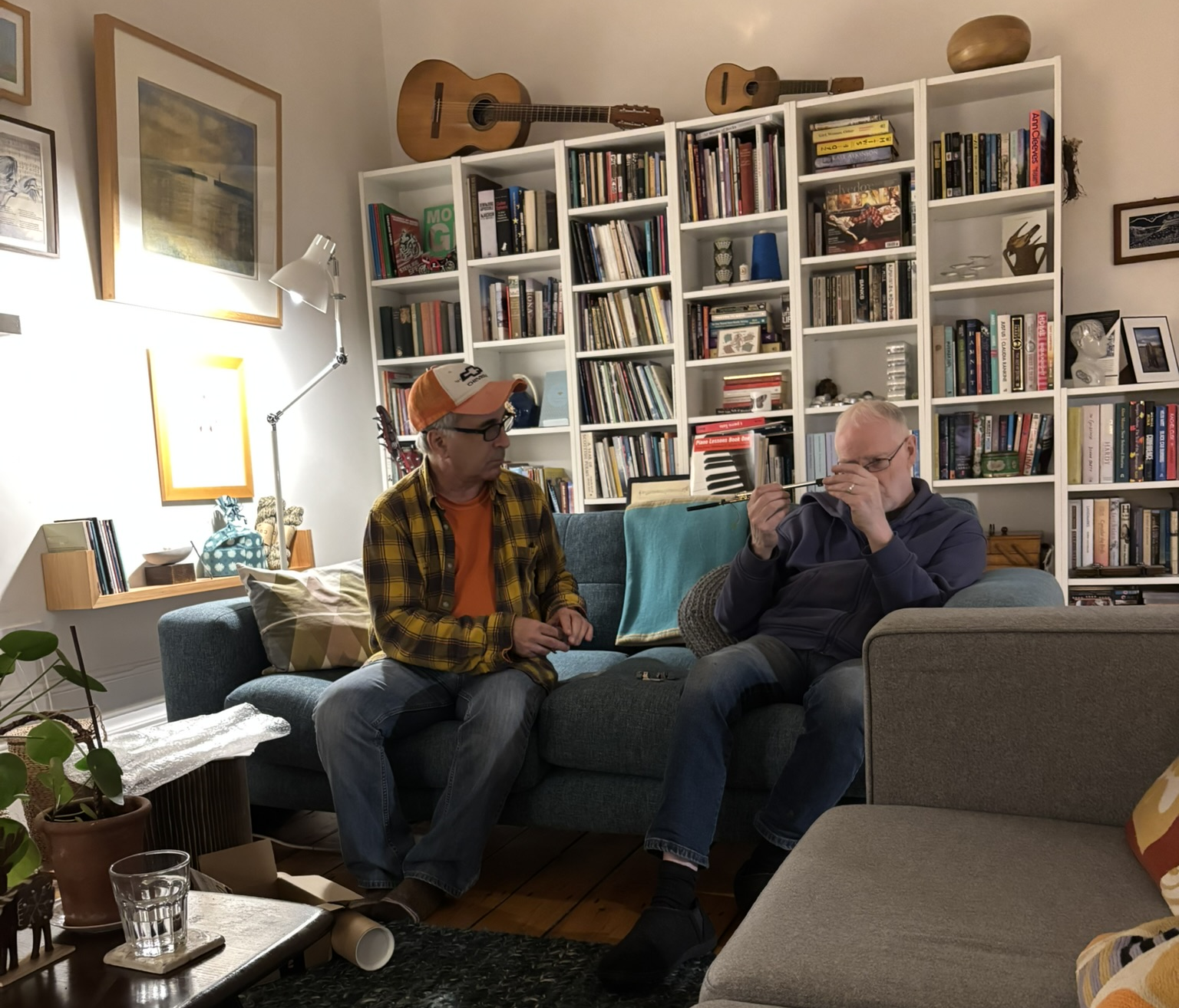
One of the first things I did before conducting any listening tests was go get my ears checked at the doctor’s office. After that, I went to the audiologist to get my hearing checked. With no issues to report and I was ready to do some serious listening and evaluation.

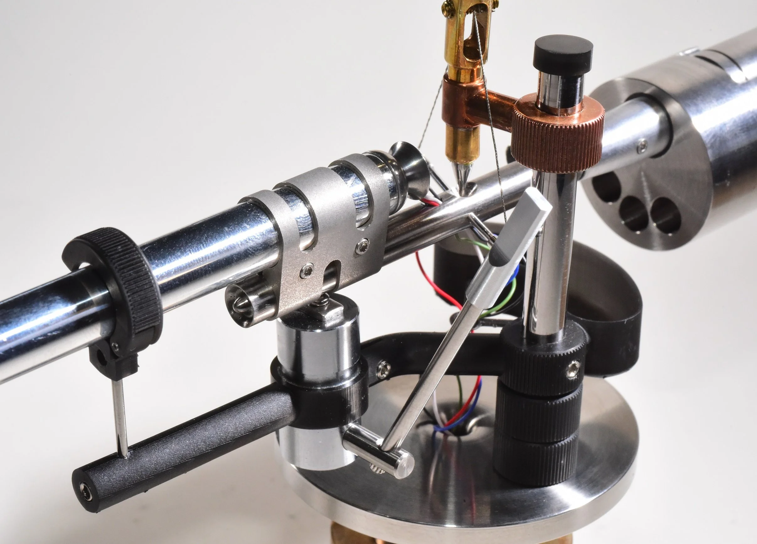
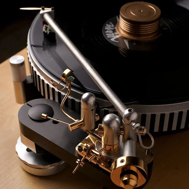
With the first working prototype assembled and mechanically validated, the UA-101 tonearm moved into its next critical phase: performance testing. Where the prototype build had confirmed that the design worked as a mechanism, performance testing would determine whether it worked as an actual high performance tonearm − whether the geometry, bearing system, and mass distribution translated into measurable precision and, more importantly, audible truth.

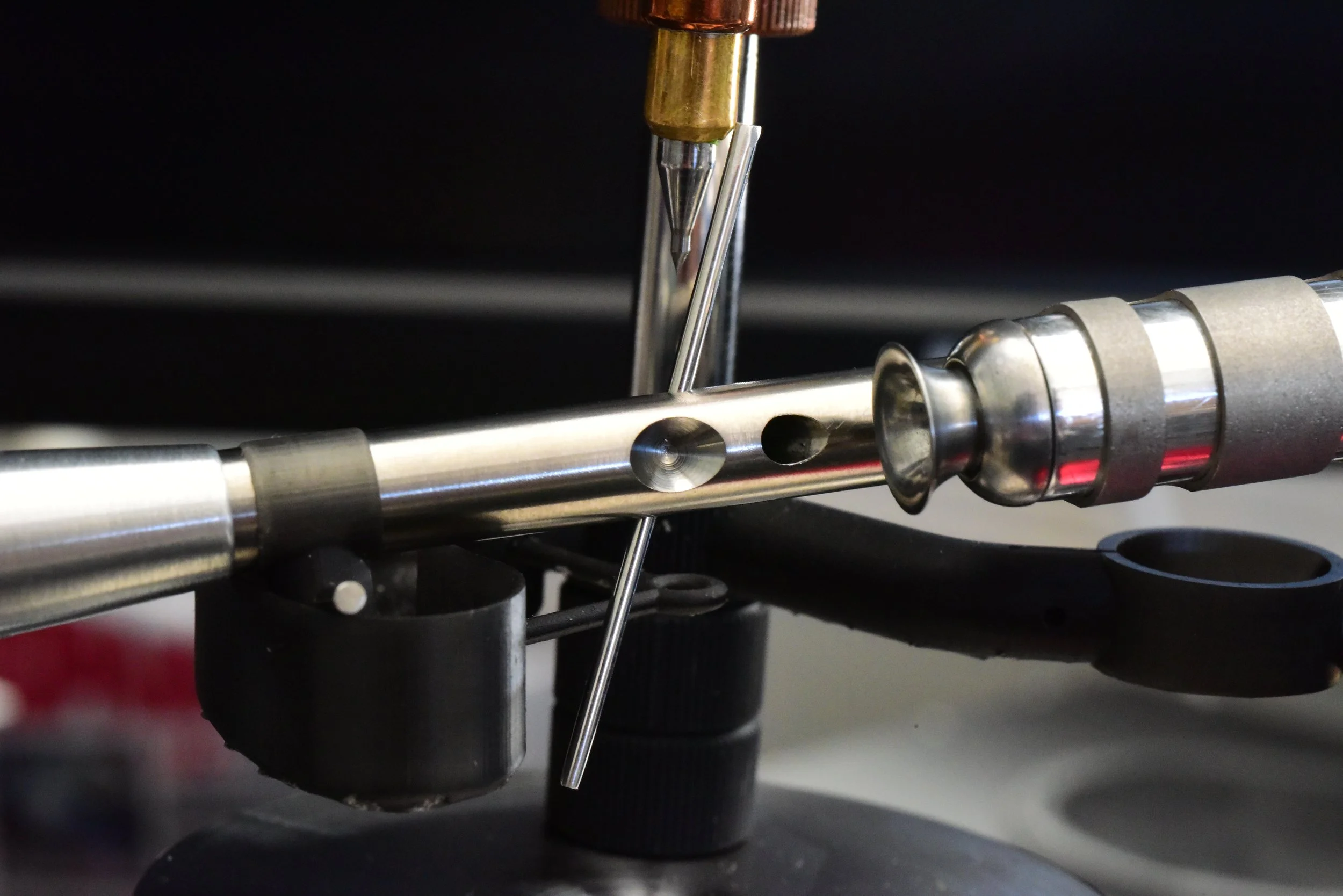
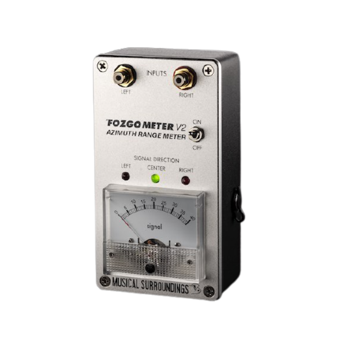
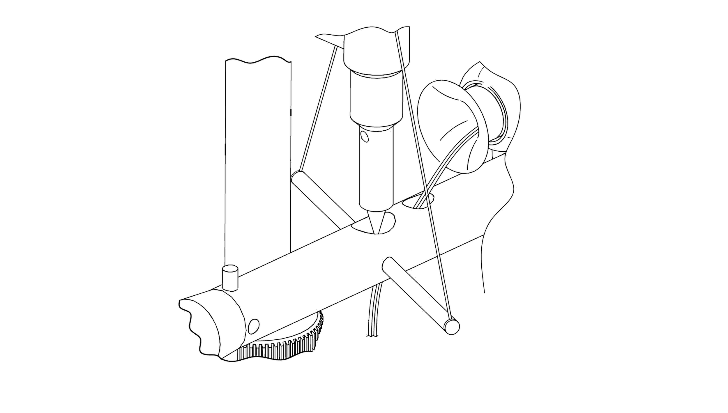
The testing protocol was designed around a core philosophy: measurement and listening must come together. A systematic, hybrid method was developed for setting cartridge azimuth − the left-right rotational alignment of the stylus in the groove − combining mechanical alignment, electrical measurement via a Fozgometer, and critical listening with musically revealing program material. The objectives were multidimensional: minimize crosstalk, maximize phase coherence, equalize groove wall contact, and optimize stereo imaging, tonal purity, and high-frequency smoothness. Numbers alone would not be sufficient. Listening would make the final determination.


The protocol unfolded in descrete stages. Stages one through three established mechanical and electrical baselines − setting vertical tracking force, vertical tracking angle, and visual azimuth, then using the Fozgometer with The Ultimate Analogue Test LP to minimize crosstalk and equalize channel leakage through fine incremental adjustments. Stages four through eight shifted to critical listening passes: mono lock-in, music verification, channel symmetry, stereo imaging evaluation, and high-frequency stress testing, each refining the azimuth position by ear around the Fozgometer-derived setting. Stages nine and ten closed the loop, re-confirming electrical measurements, verifying alignment convergence with listening results, locking the final setting, and re-checking VTF and VTA for stability.

"Azimuth calibration testing protocol flowchart showing 10 stages"


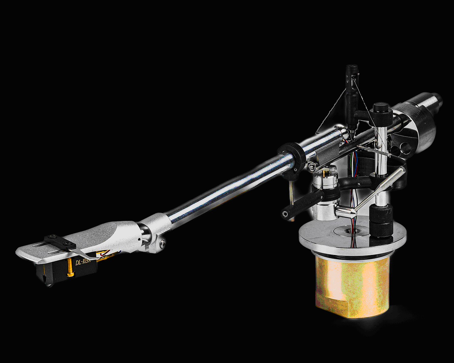
To ensure the results were not cartridge-dependent, four distinctly different cartridges were rotated through the testing: an Audio Technica AT33PTG/II, an Ortofon Kontrapunkt b upgraded with a Fritz Gyger S stylus and boron cantilever, a Denon DL-103R rebuilt with a nude line contact stylus and hardened tapered aluminum cantilever, and a Hana Umami Red. Each brought different compliance, mass, and stylus geometry to the evaluation, stress-testing the tonearm's ability to perform consistently across a range of real-world cartridge pairings.

Reference recordings were selected for tonal diversity and revealing character: Pink Floyd's Dark Side of the Moon, Steely Dan's Aja, Joni Mitchell's Court and Spark and Don Juan's Reckless Daughter, David Crosby's If I Could Only Remember My Name, Dire Straits' Brothers in Arms, and others − many in Mobile Fidelity or Nautilus pressings chosen for their superior mastering quality. The solo recorder passage opening Stairway to Heaven served as a particularly exacting azimuth reference, its rich harmonic content, sustained tones, and near-point-source imaging exposing phase smear, grain, and high-frequency harshness that denser recordings would conceal.

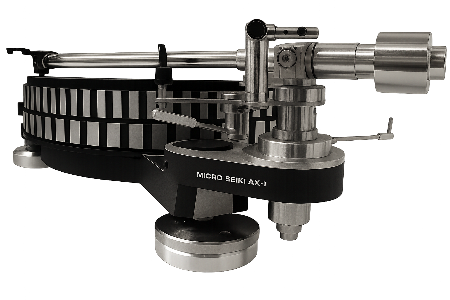
Two turntable platforms anchored the testing: a Technics SP-10 and a Micro Seiki DDX-1000, each fitted with a UA-101 prototype and custom AST stabilizer. A upgraded Audio Technica AT-1010 tonearm on the second Micro Seiki provided a comparative reference point.

The results confirmed what the first prototype build had suggested and then deepened the picture considerably. Objective measurements − crosstalk symmetry, channel separation, phase correlation, high-frequency leakage − aligned consistently with the subjective listening evaluations. Center image focus, harmonic smoothness, soundstage depth, transient cleanliness, and low-level detail retrieval all pointed to the same azimuth settings the instruments identified. Measurement and perception converged.

This first round of performance testing delivered far more than validation. It generated the detailed, cartridge-specific, musically grounded data necessary to refine tolerances, confirm design priorities, and move the UA-101 forward with confidence into its next stage of development: the pre-production prototype. So at this point, the performance testing results were simply outstanding.


For the latest blog updates, subscribe!


The Pre-Production UA-101 by Greg Viggiano

"UA-101 tonearm with stabilizer, photographed by Paul Elliott"

UA-101 with Stabilizer, photo Paul Elliott

The pre-production prototype of the UA-101 tonearm marked the moment the project crossed a critical threshold − from proving that the design could work to demonstrating that it was ready to meet the world. No more 3D printed parts. All components were now in their final final form and in the intended production materials with correct tolerances and clearances.

The transformation of going from working prototype to pre-production prototype was not just cosmetic. Every lesson extracted from the first working prototype and its subsequent performance testing had been designed into this revision. Minor issues identified in earlier resin-printed sections had been addressed through material selection and refined geometry in the machined replacements. Assembly issues that had surfaced during the proof-of-concept build were resolved with design updates. Dimensional data gathered across multiple cartridge installations and azimuth calibration cycles informed tightened tolerances on bearing housings, pivot interfaces, and alignment geometry.

The results were obvious. Every measurable parameter either met or exceeded the benchmarks established during earlier testing. More telling than the numbers, however, was the listening. Tracks that had served as diagnostic tools during performance testing − the opening recorder passage of Stairway to Heaven, the spatial complexity of Joni Mitchell's Don Juan's Reckless Daughter, the transient detail buried in Steely Dan's Aja − now revealed themselves with an ease and authority the earlier prototype had only hinted at. Center image focus sharpened. Soundstage depth gained a new sense of proportion. High-frequency air opened without grain or fatigue. The convergence between measured and perceived performance that the testing protocol had been designed to achieve was not just present − it was sort of effortless.

The pre-production prototype exceeded expectations not as a rough proof of concept outperforming its station, but as a near-finished product performing at the level the market would judge it by. It demonstrated that the UA-101 was ready for introduction − not as a promise, but as a refined, substantive instrument.

Still, the process was not quite finished. Fine-tuning remained: subtle refinements to surface treatments, final decisions on packaging and documentation details, and the last quality-control protocols that separate a superb pre-production unit from a fully production-ready product. The UA-101 had proven itself. The final stage − preparing it for consistent, repeatable production − was now clearly within reach.


For the latest blog updates, subscribe!


A Working Prototype by Greg Viggiano

UA-101 tonearm early prototype

UA-101 tonearm early prototype

The first working prototype of the UA-101 tonearm represented a significant milestone in the project's development − a moment where theories, engineering, and digital models finally came together into a physical, functioning moment of truth.

Built from a deliberate combination of CNC-machined pre-production parts, high-resolution resin-printed 3D components, and lost-wax cast metal elements, this prototype was never intended to be a finished product. It was a proof of concept, assembled to answer one fundamental question: does this design actually sound good?

The answer exceeded my expectations.

Each manufacturing method used in the first prototype served a distinct purpose. CNC-machined components provided the dimensional precision necessary for critical bearing surfaces, pivot mechanism, and geometries where tolerances needed to be exact. These parts established the mechanical foundation of the tonearm, ensuring that the critical geometries behaved exactly as required. Where form and mass distribution mattered but surface finish and final material selection were still under development, high-resolution resin-printed parts filled the gap. 3D printing allowed complex shapes and structures to be built quickly and inexpensively, making it possible to evaluate fit/finish, visual proportions, and assembly sequences without committing to machined parts. For elements requiring specific density, damping characteristics, or structural rigidity that plastic could not replicate, lost-wax cast metal parts completed the assembly. These castings captured the intended mass properties of the design and provided the structural requirements necessary for meaningful performance testing.

The result was a hybrid of polished stainless steel, tungsten, and titanium, black resin, and copper and brass castings. Although it lacked the refinement of a production unit, the first UA-101 prototype delivered tracking performance, resonance control, and dynamic behavior that went well beyond what a rough proof-of-concept build would typically produce. The bearing system exhibited the near-frictionless and mechanical performance the design predicted. The effective mass fell within the target range. Anti-skate compensation responded linearly. Cueing was smooth and controlled. Most importantly, the tonearm's fundamental geometry and alignment parameters (that John Gordon assisted with) − the relationship between its pivot point, headshell offset, overhang, and tracking angle − confirmed that the underlying engineering was viable and genuinely promising.

This stage of development was never about polished aesthetics or market readiness. It was about design and performance validation. The first prototype confirmed the design assumptions and, equally valuable, revealed where refinements were needed. Assembly sequence challenges identified opportunities to simplify production fixtures. Dimensional data gathered from the CNC and cast parts informed updated tolerances for the next revision.

The first working prototype of the UA-101 accomplished exactly what it was supposed to do. By proving the concept with tested mechanical performance, it provided the confidence and the engineering data necessary to advance to the next critical phase: the pre-production prototype, where material selections would be finalized, fit and finish elevated, and the tonearm prepared for its transition from a bench-test proof of concept to a refined, production-ready tonearm.


For the latest blog updates, subscribe!


A Trip to Glasgow, Scotland to Meet the Master by Greg Viggiano

Greg Viggiano (left) and John Gordon discuss the prototype and alignment considerations at his home, Glasgow, Scotland, December 3, 2025

Greg Viggiano (left) and John Gordon discuss the prototype and alignment considerations at his home, Glasgow, Scotland, December 3, 2025

Engineering Collaboration and the Art of Tonearm Design

Some of the most valuable resources in audio engineering don't come from textbooks or manufacturer spec sheets − they come from the quiet corners of the internet where designers and engineers generously share what they've actually learned.

Years ago, a friend in the UK audio community pointed me toward a tonearm engineering blog that I've returned to many times since. For anyone serious about understanding the functional and mechanical underpinnings that govern tonearm physics, the blog is an essential treasury of detailed research, and written by someone who has spent years figuring out all aspects of tonearm design and engineering.

That blog belonged to John Gordon, the engineer behind the Odyssey tonearm. What was very apparent wasn't just the depth of his technical knowledge, but the clarity in which he communicated it. Tonearm design sits at a particular intersection of mechanical engineering, acoustics, material science, and electrical engineering − and John's writing described all of it with the expertise of someone who has obviously spent years on the subject.

ODYSSEY TONEARMS RP1-XG Mk 1 General Arrangement

Odyssey Tonearm RP1-XG

As my own work progressed − running engineering experiments in parallel with component development and iterative prototyping − I found myself constantly referring to his blog. Questions that my own experiments raised were often addressed, at least in part, somewhere in his posts. Others, not so much.

That's when I reached out to John. What started with a series of emails, gradually turned into more technical exchanges. A couple of phone calls followed.

I had planned a pre-Christmas visit to meet my daughter in London for the Holidays and thought, if I’m going to be in the neighborhood, maybe I should make a journey to Scotland to show him the prototype. As it turned out, John was available, so my daughter and I made the trip to Glasgow.

Spending time with John at his home in Scotland was exactly the kind of experience that shows why professional collaborations matter. There is something fundamentally different about working through a complex engineering problem face-to-face, with the actual hardware sitting on his coffee table in the living room. You can point at things. You can demonstrate behavior that's difficult to describe on the phone.

An Odyssey RP1-XG Tonearm on a Micro Seiki DQX-1000 turntable

An Odyssey RP1-XG Tonearm on a Micro Seiki DQX-1000 turntable

John definitely brought a perspective informed by years of hands-on experience and suggested different design options and different problem-solving approaches than my own − and those differences are the whole point. His advice didn't always hand me a ready-made solution to my design challenges, but it did something arguably more valuable: it opened new ways of thinking I hadn't considered, reframed some assumptions I'd been carrying, and gave me a clearer sense of where to look next.

That's what good technical collaboration is all about. It may not always solve the problem − but it can change the way you see it and spur new ways thinking. I consider myself very lucky to have been mentored by John Gordon and the advice he has so generously shared with me. If I can one day master the fish curry that he made for dinner that night, I will die a happy man.

As I continue my development work, I would be pleased if I can pass this knowledge forward to the next generation of tonearm designers and see what they can do.


For the latest blog updates, subscribe!


Engineering and Design Philosophy by Greg Viggiano

From Imagination to Reality: A Systems Engineering Approach to Precision Analog Stabilized Playback

Inverted tungsten unipivot point and titanium connecting rod cup

Inverted tungsten unipivot point and titanium connecting rod cup

Every engineering project begins as an idea - a set of objectives balanced against the finite laws of physics. When I set out to design this tonearm, I had a clear set of objectives in mind: best-in-class quality, measurable performance improvement, iconic aesthetics, and, above all, the primary mission of delivering dynamic azimuth control during playback. Achieving all of those objectives required a disciplined, systems-level engineering methodology capable of simultaneously coordinating decisions across multiple interrelated technical areas.

A Systems Engineering Framework

A tonearm is deceptively complex - simultaneously an electrical circuit, a mechanical structure, an acoustic device, and a visual statement. A systems engineering approach organized my design work across five interrelated domains: material science, electrical engineering, mechanical engineering, acoustics, and industrial design. The real art lies in the arrangement, configuration, and integration of components so that gains in one domain do not adversely affect the others. This multi-domain optimization is inherently iterative, time-consuming, and very expensive. To shorten the cycle, I began with foundational assumptions drawn from established best practices and refined each through continuous prototyping. Actually, the prototyping and design of experiments never stop.

The core design targets formed an interlocking system: a stabilized unipivot bearing; a nine-inch arm (228 mm) effective length; a mechanically rigid arm tube and headshell for cartridge stability; super-low-resistance copper wiring for signal integrity; minimal energy storage in the arm tube; an effective mass of approximately 16 grams to complement the intended cartridge compliance range; and optional fluid damping matched for low-compliance cartridges. Each parameter was chosen not in isolation but with full awareness that changing any single variable will impact other parts of the system.

Guiding Design Principles

Behind every engineering decision sat a set of strict principles. Effective mass had to complement cartridge compliance to keep the resonant frequency in the ideal range. The bearing had to permit real-time azimuth mechanical adjustment while eliminating the radial-axis instability that plagues traditional unipivots, especially on tracks with deep bass and high modulation. Rigidity throughout the arm was essential for cartridge stability. Energy storage in the arm tube had to be minimized - stored energy means delayed, smeared vibration release, the enemy of transient accuracy. The electrical path had to offer the lowest possible resistance. Environmentally sensitive materials like wood were excluded from mechanical parts in favor of long-term dimensional stability. And the finished arm had to deliver setting stability with virtually no maintenance or recalibration.

From CAD to Reality: Rapid Prototyping

Elegoo Saturn 2 3D printer

This project would have been financially impossible without two critical tools: a high resolution 3D resin printer (like the Elegoo Saturn 2) and SolidWorks CAD software. Teaching myself SolidWorks was not easy, but was one of the most consequential investments I made. Together, these tools compressed the path from imagination to a testable physical prototype down to hours. Design updates that would have required weeks through a traditional machine shop became near-instantaneous and essentially free. By my estimate, the cumulative cost savings exceeded $100,000.

Dimensional precision is standardized to three decimal places for CNC-machined components and five decimal places for CAD files. Beyond that, returns diminish rapidly; the goal is precision that matters without chasing tolerances that cannot be reliably held or meaningfully measured.

The Hardest Problem: Stabilized Unipivot with Dynamic Azimuth

Solidworks Logo

The project’s defining engineering challenge was mechanically stabilizing the unipivot bearing and iIt had to accomplish two things simultaneously: permit real-time azimuth adjustment during playback and eliminate the radial-axis instability inherent in traditional unipivot designs. Without radial stability, demanding tracks with deep bass and high stylus excursion produce compromised low-frequency reproduction and degraded stereo imaging. Solving this azimuth puzzle required a lot of design iterations and is the single engineering element that really distinguishes this tonearm from all others.

Form and Function: Why Aesthetics Matter

I have always believed the job is never finished if the finished product is hard to look at. Engineering performance is the primary objective - if the arm doesn’t work, appearance doesn’t matter. But creating a genuinely iconic product can be every bit as challenging. Consider Apple’s design aesthetics under Jony Ive: precise, clean, minimalist, and unmistakably Apple. Those designs proved that uncompromising engineering and striking aesthetics are complementary, not competing, goals. That same design philosophy guides this project from counterweight to headshell.

Lessons from the Machine Shop

My years of development work have culminated in a few enduring hobby dogma principles worth repeating here: keep multiple spare parts on hand, because experimenting and testing components inevitably will break (it’s part of the process). Invest in quality tools - they cost more but make the work go easier and faster. Never go cheap on materials or processes; the outcome reflects the care invested. Practice disciplined project management with clear lists and milestones - staying organized will get the product delivered on time. And embrace a productive obsessiveness about precision, quality, and customer experience - because that is what separates an average product from an exceptional product.

With this engineering philosophy, the design validated, and the prototyping complete, the work is far from finished. Improvement is continuous, and I am rarely content to leave well enough alone.


For the latest blog updates, subscribe!


Physical and Electrical Azimuth - What Matters by Greg Viggiano

September 25, 2025

If you’ve ever tried to fine tune your stylus azimuth, you know that it’s not that easy. While the process might be fairly straightforward, in practice getting good results can be tough even for people that know what they’re doing.

Azimuth alignment involves optimizing both the physical azimuth for best groove contact and electrical azimuth for highest signal strength.

The needle has to sit properly in the groove − physical azimuth is the mechanical rotation about the arm’s axis (roll axis). Proper physical azimuth puts the cantilever axis perpendicular to the record surface so the stylus sees left and right groove-wall motion symmetrically, controlling how the stylus contacts the two groove walls. Physical azimuth strongly affects distortion, channel balance for groove-derived (vertical) information, imaging, and record wear.

Given the high performance stylus designs available today, a correct azimuth alignment is even more important. Christiaan Punter wrote a great article for HiFi Advice covering many of these advanced profiles and their attributes.

Once the physical azimuth alignment is set, you can measure and optimize the electrical azimuth / electrical output: the separation between left and right stereo signals and minimize signal leakage (crosstalk). Tools for this include test records (ie. The Ultimate Analogue Test LP, Side 1, Track 1, Track 2, and Track 3) and devices like a Puffin, Fozgometer, or AnalogMagik software, to determine actual channel balance. The best electrical azimuth may not look perfectly level but gives the truest stereo image and channels separation. Electrical azimuth calibration is recommended for precise channel separation and stereo imaging, as the physical look may not always match the internal coil alignment.

fozgometer signal meter
Ultimate Analogue Test LP

Caveat: If the stylus and cantilever are physically out of alignment from the factory and not within the manufacturer’s tolerances, a few problems will occur:

  1. One channel will be more sensitive to vertical groove motion than the other → channel level/tonal imbalance on certain material;

  2. Inter-channel phase/phase-response errors increase → smeared imaging and poor mono compatibility (some frequencies cancel when summed);

  3. Increased harmonic distortion, mistracking, and uneven record/stylus wear (this causes physical, permanent damage).

You can’t correct bad geometry with electronics − electronics will only mask the symptoms (EQ/gain), it cannot restore correct stylus/groove geometry or prevent abnormal groove wear.


The Two Step Calibration Process

Basically, there’s two approaches to setting stylus azimuth − visually and electrically. Both are important. Assuming that the stylus and cantilever have been manufactured correctly (which is actually a big assumption), and the coils inside the cartridge are correctly positioned, the best way to calibrate stylus azimuth involves a two-step process.

The first step is to visually align the cantilever so it is perpendicular to the record surface (you can use a mirror under the cartridge to see if the cantilever and its reflection form a vertically straight line perpendicular to the record surface).

The second step involves adjusting the electrical azimuth. This step focuses on channel separation and crosstalk − the leakage of signal from one channel to another. Measurement requires a test record, voltmeter, or specialized electronic tools (e.g., Puffin, Fozgometer, software), listening to, or measuring one channel while only the other is modulated.

The optimal setting is when crosstalk is minimized and both channels are evenly balanced for the best stereo separation (even if the cartridge or stylus may look slightly "tilted" visually).

Because the internal structures of the cartridge (such as the coils, yoke, and cantilever/stylus) may not visually align with the cartridge body, only electrical measurements can ensure true channel balance and separation at playback.


The Issue

The main issue with this two-step calibration process is that it requires several “test-set-test” cycles and makes it difficult to determine the best signal performance for each channel because of the need to repeat and reconfirm the last test.

“There’s got to be an easier way to do this . . . “

So I figured, if Micro Seiki did it with dynamic VTA and dynamic VTF, maybe it’s possible to dynamically set the azimuth while a record is playing. Then you could actually see in real time the peak signal strength while playing a 1kHz test track − without taking the needle out of the groove to readjust the headshell.


The Solution

Tonearm connecting rod and pivot point

Solving this engineering puzzle required using a stabilized unipivot bearing that would allow adjusting the roll axis of the stylus and cantilever independently from the pitch axis and the yaw axis − while retaining frictionless pitch and yaw freedom of movement as the record is playing.

The offset angle of the headshell matches the offset angle of the bearing which is dependent on the effective length of the arm’s stylus to pivot distance. Also, the stabilized unipivot bearing is positioned on the same horizontal plane as the record groove. This arrangement allows the stylus azimuth to have the correct geometry when making azimuth adjustments from a rotary control above the stabilized unipivot.


For the latest blog updates, subscribe!


Just Another Micro Seiki Disciple by Greg Viggiano

There is something about Micro Seiki’s engineering and aesthetics that have always resonated with me.

A Micro Seiki DDX-1000 turntable  with an MA-505 tonearm

A Micro Seiki DDX-1000 turntable
with an MA-505 tonearm

I guess everything started in the late 70s when I was in high school, making weekend trips to Tech HiFi, the local stereo shop in Rochester Michigan. It was there that I had my first look at a Micro Seiki DDX-1000 and its three tonearms. I’ve been fascinated ever since.

My fascination with this turntable resurfaced on my 50th birthday when my wife found one on Craig’s List in San Francisco. It was in excellent shape with a beautiful MA-505 dynamic tonearm − and that’s when another fascination started with the MA-505. This tonearm debuted in September 1976, 50 years ago and was fully adjustable while the record was playing: VTA, VTF, and anti-skate. Besides being a pretty arm, the engineering was extremely clever.

Over the last few years, I’ve rebuilt and rewired a few of these arms giving me a better understanding of their engineering − including the tungsten cable (not a wire) for the dynamic vertical tracking force adjustment. Using a low power microscope, the cable is actually comprised of 24 individual tungsten micro filaments.

At one point while I was restoring a dynamic VTF mechanism, it occured to me how interesting a dynamic azimuth control mechanism would be − given how difficult it is to properly calibrate that setting.

My initial thoughts focused on how to re-design and re-engineer the pivot and the pivot position. I needed the new geometry to accurately align the stylus in the 50-micron wide record groove and the stylus rotational axis to align with the pivot point on the same horizontal plane with a matching offset angle.

As I thought through various engineering solutions, I knew that a gimbaled bearing would probably not provide the longitudinal rotational capability, and a traditional unipivot totally lacked lateral stability . . . what I needed was an adjustable and completely stabilized unipivot bearing.

This is where the engineering puzzle started to come together.

The 1979 Tech HiFi Catalog signed by  John Strohbeen, owner of Tech HiFi and  Ohm Acoustics Corporation.

The 1979 Tech HiFi Catalog signed by
John Strohbeen, owner of Tech HiFi and
Ohm Acoustics Corporation.

Page 38 featuring a signature system with a Micro Seiki DDX-1000, The MSRP of this turntable was $650 in 1979.

Page 38 featuring a signature system with a Micro Seiki DDX-1000, The MSRP of this turntable was $650 in 1979.


For the latest blog updates, subscribe!


Introduction and Background: A Tonearm with Dynamic Azimuth Control by Greg Viggiano

This project started in 2023 as a tonearm engineering puzzle to figure out how to dynamically calibrate stylus azimuth on the record groove level with correct and stable geometry while the record is playing.

This blog chronicles the project’s progress, prototype fabrication, and functional enhancements leading to a new tonearm innovation for the audio community.

So, why is dynamic azimuth so important?

"UA-101 tonearm wireframe rendering showing headshell, arm tube end, and pivot housing"

Modern stylus profiles are a lot more sophisticated compared to 40 years ago. These newer profiles require very precise alignments to position the needle in the groove to deliver maximum performance - if not properly aligned, it’s like a driving race car with bad wheel alignment. It becomes very obvious, very quickly.

Of all the tonearm settings, azimuth is probably the trickiest to correctly calibrate and even more so with traditional unipivot tonearms (and this assumes that your MC cartridge’s coils are properly aligned). The difficulty comes from a mix of geometry, mechanics, and perception. Here’s why:

1. Microscopic Scale of the Problem

∙ The azimuth is the side-to-side tilt of the cartridge/stylus in the groove.
∙ A tiny angular misalignment (fractions of a degree) can cause uneven contact of the stylus with the groove walls.
∙ Because LP grooves are only 50 microns wide, even the slightest misalignment produces audible
channel imbalance, crosstalk, or distortion.

2. Interaction of Multiple Variables

Cartridge manufacturing tolerances: The stylus tip, cantilever, and body are not always perfectly aligned.
Even if the headshell looks level, the diamond or coils may not be.
Headshell and tonearm machining tolerances: Small imperfections in the arm or mounting hardware
compound the problem.
Record warps and off-center pressings: They dynamically shift the stylus angle, masking or complicating setup.

3. Lack of a Universal Reference

∙ Unlike tracking angle or tracking force (which have measurable standards), azimuth has no absolute “zero” point.
∙ A cartridge may appear visually level but still be electrically or mechanically misaligned.
∙ This forces users to rely on test records, electronic measurement (oscilloscope, software, Fozgometer, Puffin, etc.),
or trial-and-error listening.

4. Difficult Measurement and Verification

∙ Professional azimuth setup often involves measuring crosstalk between left and right channels with
precision measurement equipment.
∙ For most audiophiles, relying on listening tests can be subjective and inconsistent, since
small changes may sound better on some records but worse on others.
∙ Visual alignment using a mirror or bubble level is rarely accurate enough at the stylus tip.

5. Mechanical Challenges

∙ Many tonearms allow azimuth adjustment, but many don’t allow calibrated fine azimuth adjustment.
∙ When they do, the mechanism may be crude (loosening set screws, rotating the headshell, or shimming),
which risks damaging the cartridge or introduces play and instability.
∙ Typical unipivot tonearms are especially tricky because their resting azimuth changes with
high modulation grooves, tracking force, anti-skating, and arm balance.

In short: Setting azimuth is difficult because you’re trying to align a microscopic diamond to the groove walls with sub-degree precision, without a clear universal reference point, using mechanical systems that are not always precise or stable.

So, what if you had a way to see and hear the azimuth calibration coming into alignment as a record is playing . . .


Intended Outcomes

The objectives for this project are fairly straightforward and listed below:

  1. Introduce a new, high performance tonearm innovation

  2. Develop a new azimuth control mechanism to provide correct and stable geometry, via a near-frictionless, stabilized unipivot bearing positioned on the same plane as the record for precise record groove tracking

  3. Deliver obvious audible improvements when making real-time azimuth adjustments on the record groove level

  4. Use the highest quality precision CNC machining and material components

  5. Design the product to be durable and easy to use

  6. Provide an easy setup procedure and installation (fully adjustable) with clear support documentation, and reliable customer service

  7. Develop an attractive product design with iconic high-end vintage aesthetics


About Me: Greg Viggiano

Much of my career has involved technology and software product management. Over the last several years, I have been doing academic research on the potential impacts of AI and quantum computing as these two technologies begin to converge.

Currently, I am an adjunct professor at George Mason University, Department of Physics and teach graduate and undergraduate classes on new technologies and social impacts. My research interests focus on new technology applications and macro social effects. In addition to my academic career, I am also the pro bono Executive Director for the Museum of Science Fiction in Washington, DC.

When I’m not teaching and doing social science research on AI and quantum computing, I like to restore vintage turntables for my ever expanding record collection. I received my PhD from Florida State University in Mass Communication and live in Alexandria, Virginia.


For the latest blog updates, subscribe!